VFR Navigation Charts and Required Documents
Before a VFR navigation flight, you need current aeronautical charts and the appropriate aircraft documents. Charts help you identify airports, airspace, terrain, obstacles, and visual landmarks.
Always check the effective dates of your charts and publications. Document requirements depend on the aircraft, country, and type of flight.
VFR Charts Used in the United States
Sectional Aeronautical Chart
FAA Sectional Charts are used for visual cross-country navigation. They show airports, airspace, navigation aids, terrain, obstacles, and landmarks.

Terminal Area Chart (TAC)
Terminal Area Charts provide more detail around selected busy airports and terminal areas. They help pilots examine complex airspace and airport information more closely.
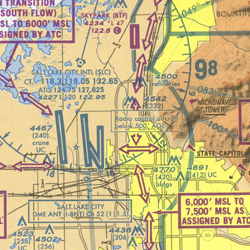
A VFR chart does not show every detail needed for an airport visit. The FAA Chart Supplement provides airport information such as runways, communications, services, and local procedures.
Check the current information for departure, destination, and possible diversion airports.
Official reference: FAA Chart Supplement.
NAV CANADA publishes VFR Navigation Charts (VNC) at a scale of 1:500,000. They are used for visual cross-country navigation.
VFR Terminal Area Charts (VTA) provide more detail around selected busy terminal areas, at a scale of 1:250,000.
The Canada Flight Supplement (CFS) provides airport and operational information.
What Should You Look for on a VFR Chart?
Before using a chart for flight planning, make sure you can identify the following information.
Identify airports, airspace boundaries, controlled airspace, and areas with special restrictions.
Look for high terrain, towers, and other obstacles. Check charted elevations and obstacle heights.
Find lakes, roads, towns, rivers, and other features that can help you recognize your position.
Use the chart legend and the FAA Aeronautical Chart Users' Guide to understand unfamiliar symbols, colors, and abbreviations.
Aircraft Documents to Check Before Flight
Before departure, check the documents required for the aircraft and the planned operation. The list below also includes documents that become necessary for certain international or Canadian flights.
Confirms that the aircraft has the appropriate airworthiness approval. A valid certificate must be carried and displayed as required by U.S. regulations.
USA / CANADAIdentifies the aircraft's registration. Check that the required registration document is valid and on board.
USA / CANADAAn individual FCC aircraft station license is normally not required for ordinary domestic flights in the U.S. It may be required for international operations.
Canadian aircraft must carry a radio license or copy when one has been issued for equipment operated on board.
INTERNATIONAL / WHEN APPLICABLEProvides approved operating information, limitations, procedures, and performance data. Carry or have available the manual and limitations required for your aircraft.
USA / CANADAUse the aircraft's current weight and balance information to confirm that the planned loading remains within approved limits.
FLIGHT PREPARATIONKnow how to recognize and respond to an interception. This is especially important for international operations.
Use the applicable interception procedures and required aeronautical publications. Do not assume a separate "Interceptor Order" document is mandatory for every domestic VFR flight.
INTERNATIONAL / WHEN APPLICABLEThe pilot must have the required pilot certificate or license, medical qualification when applicable, and photo identification as required by the country of operation.
USA / CANADACanada requires applicable liability insurance, and pilots operating in Canadian airspace must be able to provide the required proof.
Insurance requirements for U.S. domestic operations may differ.
CANADA / WHEN APPLICABLEUnder Canadian rules, the aircraft journey log is normally carried on board. An exception may apply when the aircraft is not planned to land and shut down anywhere other than its departure point.
A standard U.S. domestic training flight does not have the same general journey logbook carriage requirement.
CANADAThis is a preparation checklist, not a universal list of documents that every aircraft must carry. Requirements depend on aircraft registration, the country of operation, and whether the flight is domestic or international.
Charts, navigation logs, and electronic flight bags are important planning tools. They do not replace required aircraft certificates or operating limitations.
Know which aeronautical charts cover your planned route. Understand their basic symbols and confirm that the aircraft and pilot documents required for your flight are available.
Aircraft Weight and Balance
Before every flight, confirm that the airplane is within its approved weight and balance limits. An overloaded or incorrectly balanced airplane may be difficult to control and may not perform as expected.
Correct weight and balance means that the maximum allowable weight is not exceeded and the center of gravity (CG) remains within its approved limits. Both conditions must be satisfied.

Understanding Weight and Center of Gravity
Maximum Allowable Weight
The total aircraft weight includes the airplane, occupants, baggage, equipment, and fuel.
Make sure the planned takeoff and landing weights remain within the approved limits.
Center of Gravity (CG)
The CG is the point at which the airplane's weight is considered to be concentrated.
Its position changes when passengers, baggage, or fuel are added, removed, or moved.
Weight, Arm, and Moment
Three values are used in a standard weight and balance calculation: weight, arm, and moment.
Weight is the load being carried. Arm is its distance from the aircraft's reference datum. Moment describes the turning effect of that weight around the datum.
Worked Example — Calculate the CG
The following example uses hypothetical values in pounds and inches. It illustrates the calculation method, not the approved loading limits of a specific airplane.
| Item | Weight (lb) | Arm (in) | Moment (lb-in) |
|---|---|---|---|
| Empty aircraft | 1,500 | 40 | 60,000 |
| Front occupants | 340 | 37 | 12,580 |
| Rear occupant | 120 | 73 | 8,760 |
| Baggage | 40 | 95 | 3,800 |
| Usable fuel (48 US gal) | 288 | 48 | 13,824 |
| Total | 2,288 | — | 98,964 |
First, add all the weights and moments. Then calculate the CG position:
The final step is to compare 2,288 lb and 43.25 in with the approved weight and CG envelope in the aircraft POH/AFM. A calculation alone does not establish that the loading is legal.
Fuel is consumed during flight, reducing the aircraft's total weight. Depending on fuel tank locations and the aircraft design, the CG may also move.
Check the loading conditions required by your POH/AFM, including takeoff and landing.
Forward and Aft Center of Gravity
An aircraft may be within its maximum weight limit but have a CG that is too far forward or aft. Both situations can affect handling and flight safety.
Center of Gravity Too Far Aft

An aft CG generally reduces longitudinal stability. The airplane may feel more sensitive in pitch, and stall recovery can become more difficult.
Beyond the aft CG limit, sufficient nose-down elevator authority may not be available for safe recovery.
Center of Gravity Too Far Forward

A forward CG generally increases longitudinal stability but can require greater elevator control force.
Rotation and landing flare may become more difficult. A forward CG can also increase stall speed and reduce performance.
An airplane that is outside its approved CG envelope is not correctly loaded, even if its total weight is below the maximum allowable weight.
Adjust passenger seating, baggage, or fuel loading as permitted by the aircraft limitations before departure.
Final Weight and Balance Check
Before departure, complete these checks using the aircraft's current weight and balance records.
Use the current aircraft records, including installed equipment.
Include occupants, baggage, equipment, and fuel.
Determine the total weight, total moment, and resulting CG.
Confirm that the aircraft remains within the permitted weight and CG envelope for the required stages of flight.
Always check both aircraft weight and center of gravity. Calculate the moments, determine the CG, and compare the result with the approved limits for your airplane.
Select Your Route and Navigation Checkpoints
Once you have reviewed the weather, aircraft documents, and weight and balance, the next step is to plan your route on a current VFR aeronautical chart.
Your goal is to select a practical route between two airports, recognize useful landmarks, identify airspace and terrain considerations, and divide the route into manageable navigation legs.
Our Example — A VFR Flight Across California
We will use this flight as an example throughout the navigation planning process. The airports are real, but the route, selected checkpoints, and flight data must be verified on current charts.
This example follows the general direction of California's Central Valley. Towns, roads, and other recognizable features offer possible visual checkpoints.
Step 1 — Locate the Airports on Your Sectional Chart
Open the current FAA Sectional Chart covering your flight area. Find the departure airport, destination, and surrounding terrain.
Before drawing the route, review both airports' information in the Chart Supplement. Identify any nearby controlled airspace, special-use airspace, or other restrictions that could affect your route.
Find KMOD and KFAT on the current San Francisco Sectional Chart. Review the airspace surrounding both airports. Do not assume that a straight line between them is automatically an acceptable route.
Official resources: FAA VFR Charts and FAA Chart Supplement.
Step 2 — Select a Practical Route
Start by drawing a light straight line between your departure and destination airports. Then examine whether the route needs to be changed.
Check controlled airspace boundaries, prohibited and restricted areas, military operations areas, and relevant temporary restrictions. Plan for the clearances, communication, and equipment required along the route.
Look for high terrain, towers, and other obstacles. Note the highest relevant elevations along each possible navigation leg.
Consider terrain clearance, airspace, expected clouds, and the direction of flight. Apply the relevant FAA altitude rules. Confirm the final altitude during aircraft performance planning.
Locate airports along or near your route that could provide an alternative if you need to change your plans. Check their suitability and available services.
At this stage, you are choosing where you intend to fly. Do not calculate final magnetic headings or groundspeeds yet. These calculations require the selected track, aircraft performance, and forecast winds.
Step 3 — Choose Your Set Heading Point
A set heading point (SHP) is a recognizable position from which you begin following a planned navigation leg.
Instead of starting your cross-country timing immediately after takeoff, you can navigate to a clearly identifiable point, establish your planned heading, and begin tracking your progress from there.
Look for a clear landmark outside the immediate airport traffic pattern, such as a distinctive road intersection, river crossing, or other charted feature. The point should be easy to recognize and compatible with local departure procedures and airspace requirements.
Step 4 — Select Visual Checkpoints
Checkpoints help you confirm that you are following your planned track. Choose features that are visible, easy to identify, and reasonably spaced along your route.
Major highways, railway junctions, and distinctive intersections can be useful references.
Recognizable towns and airfields can help establish your position. Check their exact charted locations.
Lakes, rivers, coastlines, reservoirs, and terrain features can provide strong visual references.
Examine Turlock, Merced, Madera, and the Highway 99 corridor as possible references. Their usefulness depends on the route you actually draw.
Do not force the airplane to fly directly over every town. Select checkpoints that support a safe, practical route and can be identified confidently from your intended altitude.
Step 5 — Draw the Route and Mark Your Checkpoints
Once the route is selected, draw the navigation legs on your chart. Use a ruler and a fine pencil or suitable digital planning tools.

Mark your planned departure route from the airport to the set heading point.
Connect the SHP to the next turning point or destination. Keep the route as simple as practical while considering airspace, terrain, and other restrictions.
Add distance references at suitable intervals, such as every 10 NM. Mark the midpoint of each leg and identify your selected checkpoints.
If using the paper-chart method, draw 10-degree drift lines from suitable reference points. These will help you recognize and estimate track errors during flight.
A simplified example of chart annotations. The blue line is the intended track, while the dashed lines illustrate 10-degree drift references. This drawing is not an aeronautical chart and is not intended for navigation.
Step 6 — Measure Distance and Determine True Course
For each planned navigation leg, measure the distance in nautical miles using the correct chart scale. A plotter can also be used to measure the true course.
The true course is the intended direction of the route measured clockwise from true north. Wind correction and magnetic variation will be applied later when calculating the actual heading to fly.
The line you draw on the chart gives your intended ground track. It does not automatically give the compass heading you will fly. Wind and magnetic effects must still be considered.
Step 7 — Prepare Your Route Information
Before moving to aircraft performance and wind calculations, record the basic information for each leg.
| Route Information | What to Record |
|---|---|
| Departure and destination | KMOD and KFAT for this example |
| Set heading point | Selected visual landmark near departure |
| Navigation legs | Route segments and turning points |
| Checkpoints | Recognizable visual references |
| Leg distances | Measured nautical miles |
| True course | Measured for each navigation leg |
| Terrain and obstacle information | Minimum safe altitude considerations |
| Airspace and radio information | Relevant requirements and frequencies |
| Other landing options | Suitable airports along or near the route |
Use current FAA aeronautical charts, airport information, NOTAMs, and applicable regulations. Check any restrictions and communication requirements affecting your chosen route.
The example route in this lesson is for training. Final tracks, distances, checkpoints, altitudes, and procedures must be established using current aeronautical information.
You should now have a planned route showing your set heading point, turning points, visual checkpoints, leg distances, and true courses. You should also know the main airspace and terrain considerations.
The next step is to use this route to calculate aircraft performance, including takeoff, climb, cruise, descent, and landing.
Calculate Aircraft Performance for Your Route
Your VFR route and checkpoints are now selected. The next step is to check whether your airplane can safely complete the planned flight under the expected conditions.
Use your aircraft's Pilot's Operating Handbook (POH) or Airplane Flight Manual (AFM) to determine takeoff, climb, cruise, descent, and landing performance.
We will continue using this California route throughout the lesson. The calculations shown below are training examples. Always use the performance charts and operating procedures for the specific airplane being flown.
Check Takeoff Performance
Begin at your departure airport. Determine whether your airplane can safely take off from the expected runway at KMOD.

Takeoff weight, pressure altitude, temperature, wind component, runway slope, and surface condition.
Expected ground roll and total takeoff distance to clear the specified obstacle height, when provided by the POH/AFM.
Read the applicable takeoff performance chart. Interpolate between values and apply any corrections specified by the manufacturer.
Ground roll is the distance traveled along the runway before liftoff. Total takeoff distance includes the distance required to reach the specified obstacle height, when that performance is published.
Compare the required takeoff distance with the runway distance available and allow an appropriate safety margin.
Calculate Time, Fuel, and Distance to Climb
After takeoff, the airplane must climb to your selected cruising altitude. Before departure, you need to know approximately how long this climb will take, how much fuel it will use, and how far the airplane will travel.

Imagine you are planning our VFR flight from Modesto (KMOD) to Fresno (KFAT).
Modesto is close to sea level, and you have selected a cruising altitude of 5,500 ft MSL. The exact calculation will depend on the airport's pressure altitude and the conditions expected on the day.
- How many minutes will it take to reach cruising altitude?
- How much fuel will the climb consume?
- How many nautical miles will the airplane travel during the climb?
Step 1 — Understand the POH Climb Chart
Many aircraft POH climb charts provide cumulative time, fuel, and distance values from sea level to a specified pressure altitude.
This means that the figures shown at 5,500 ft can represent the entire climb from sea level to 5,500 ft, not just a portion of that climb.
Suppose the corrected POH chart for our hypothetical training airplane provides these values:
| Pressure Altitude | Total Time | Total Fuel | Total Distance |
|---|---|---|---|
| Sea level | 0 min | 0 gal | 0 NM |
| 5,500 ft | 14 min | 1.8 gal | 18 NM |
If the airplane were departing from sea-level pressure altitude, reaching 5,500 ft pressure altitude would take approximately 14 minutes, consume 1.8 gallons, and cover 18 NM, under the assumptions of this example.
Step 2 — What If the Airport Is Above Sea Level?
Most airports are not exactly at sea level. If the chart gives cumulative values from sea level, you must remove the portion of the climb that would already have occurred below your departure pressure altitude.
For example, imagine you are departing from an airport with a pressure altitude of 1,000 ft and climbing to a pressure altitude of 5,500 ft.
The hypothetical chart gives:
| Pressure Altitude | Total Time from Sea Level | Total Fuel from Sea Level | Total Distance from Sea Level |
|---|---|---|---|
| 1,000 ft | 2 min | 0.3 gal | 2 NM |
| 5,500 ft | 14 min | 1.8 gal | 18 NM |
You are not climbing from sea level. Your climb starts at 1,000 ft. Therefore, subtract the values at 1,000 ft from those at 5,500 ft.
The climb will take approximately 12 minutes.
The climb will consume approximately 1.5 gallons.
The climb distance is approximately 16 NM under the chart assumptions.
Step 3 — Apply This to Our Flight from KMOD
KMOD is at approximately 100 ft field elevation, which is close to sea level. However, field elevation is not necessarily the same as pressure altitude.
For the actual flight, determine the departure pressure altitude using the airport elevation and altimeter setting. Determine the cruise pressure altitude using the expected atmospheric conditions.
Then read or interpolate the appropriate values in the aircraft's climb chart, following the published instructions.
Step 4 — Record the Results
Once you have calculated the climb, keep the three values for the next stages of flight planning:
- Climb time: estimate when the airplane will reach cruising altitude.
- Climb fuel: include fuel consumed during the climb in the flight's fuel plan.
- Climb distance: estimate where along the route the airplane will reach cruising altitude.
The numbers above are hypothetical and do not come from the displayed POH chart. Use the specific aircraft data and apply all published corrections.
Climb charts may use a particular wind assumption. A headwind reduces ground distance covered during a given climb time, while a tailwind increases it.
Follow the POH instructions and account for forecast winds before using climb distance in your navigation plan.
Determine Cruise Performance
Once the airplane reaches cruising altitude, you need to know its expected speed and fuel consumption at the selected power setting.

True airspeed is the airplane's speed through the surrounding air.
You will combine TAS with forecast winds to calculate the expected groundspeed and heading for each navigation leg.
Fuel flow is the amount of fuel the airplane consumes per hour at the selected cruise power setting, expressed in gallons per hour (GPH).
For example, 8 GPH means the airplane consumes approximately 8 gallons of fuel per hour at that power setting.
You will use this figure to calculate cruise fuel requirements once the enroute flight times are known.
At this stage, record the TAS and cruise fuel flow from the POH. We are not calculating the final groundspeed yet, because that requires wind correction for the planned route.
Plan the Descent
Before arriving at KFAT, determine approximately when you should begin descending from cruising altitude.
A planned descent allows you to reach the appropriate arrival altitude without needing a rushed or unnecessarily steep descent.
Suppose you need to lose 4,000 ft before reaching your planned arrival altitude.
You select an average descent rate of 500 ft/min, consistent with your airplane's operating guidance.
Assume an average descent groundspeed of 100 kt.
You would need approximately 13 NM to complete this descent under the assumed conditions.
This estimate does not include additional distance for arrival procedures, traffic sequencing, or maneuvering. Refine it using the expected wind, aircraft guidance, and planned arrival.
Simplified flight profile showing climb, cruise, and descent. Not drawn to scale.
Check Landing Performance
The final performance check concerns the destination airport. Use the aircraft's expected landing weight and the conditions forecast at KFAT.

Determine the expected distance from touchdown to a complete stop under the specified chart conditions.
Where published, determine the landing distance from the specified obstacle height to a complete stop.
Consider landing weight, pressure altitude, temperature, wind, runway slope, and runway surface condition. Apply the POH/AFM corrections and appropriate safety margins.
Compare the calculated landing distance with the landing distance available. Higher weight, tailwind, high density altitude, and unfavorable runway conditions may increase the landing distance.
Record Your Aircraft Performance Data
At the end of this stage, collect the results that you will need when completing your navigation calculations.
| Flight Phase | Value to Record | Source |
|---|---|---|
| Takeoff | Ground roll and total takeoff distance | POH/AFM takeoff chart |
| Climb | Time, fuel, and distance to cruising altitude | POH/AFM climb chart |
| Cruise | True airspeed and fuel flow | POH/AFM cruise chart |
| Descent | Estimated descent time, ground distance, and fuel allowance | Aircraft guidance, performance data, and planning calculations |
| Landing | Landing ground roll and total landing distance | POH/AFM landing chart |
Under 14 CFR § 91.103 , pilots must become familiar with the available information concerning the planned flight, including applicable runway and performance information.
You should now have checked takeoff and landing performance, calculated the expected climb, selected cruise TAS and fuel flow, and estimated the descent.
The next step is to combine your planned true courses, aircraft TAS, and forecast winds to calculate headings, groundspeeds, and estimated flight times for each navigation leg.
Calculate Headings, Groundspeed, and Flight Times
You have drawn your route on the sectional chart and selected a cruising true airspeed (TAS) from your aircraft's performance data. Now you must calculate the heading to fly, the expected groundspeed, and the time required for each navigation leg.
Before using the E6B flight computer, review the navigation terms and speeds you will use during these calculations.
Navigation Terms — From Track to Heading
Track describes the direction of movement over the ground. Heading describes the direction the airplane's nose points. Wind can make the two directions different.
| Order | Navigation Term | Definition | Use in Flight Planning |
|---|---|---|---|
| 1 | True Course (TC) | The direction of the intended ground track, measured clockwise from true north. | Draw the route on the sectional chart and measure the true course. |
| 2 | True Heading (TH) | The direction the airplane's nose points, measured clockwise from true north. | Apply the wind correction angle to the true course. |
| 3 | Magnetic Variation | The angular difference between true north and magnetic north. | Use the charted variation to convert true directions to magnetic directions. Subtract east variation; add west variation. |
| 4 | Magnetic Course / Track | A ground-track direction measured relative to magnetic north. | Convert the true course to a magnetic course. This still describes the route, not the direction the nose points. |
| 5 | Magnetic Heading (MH) | The direction the airplane's nose points, measured clockwise from magnetic north. | Convert true heading using magnetic variation. This is the heading normally used with magnetic navigation references. |
| 6 | Compass Deviation | Magnetic compass error caused by magnetic influences in the airplane. | Use the aircraft's compass correction card. |
| 7 | Compass Heading (CH) | The heading indication required on the aircraft's magnetic compass, after accounting for deviation. | Use this indication when navigating by the magnetic compass. |
Imagine your planned true course is 150°. With no crosswind, your true heading may also be 150°.
If a crosswind pushes the airplane to the left, you must point its nose slightly to the right to remain on the planned ground track.
The actual track is the path the airplane really follows. It may differ from the planned course if your wind correction is inaccurate.
Navigation Speeds — IAS, CAS, TAS, and GS
These four speeds have different meanings. During navigation planning, the most important distinction is between true airspeed and groundspeed.
| Order | Speed | Definition | Use in Navigation |
|---|---|---|---|
| 1 | IAS — Indicated Airspeed | The airspeed displayed on the airplane's airspeed indicator. | Used to fly the airplane at the appropriate climb, cruise, or approach indicated airspeed. |
| 2 | CAS — Calibrated Airspeed | IAS corrected for instrument and position errors. | Use the aircraft's airspeed calibration chart when CAS is needed. |
| 3 | TAS — True Airspeed | The airplane's speed relative to the surrounding air mass. | Obtain TAS from the aircraft's performance data or appropriate airspeed corrections. Enter TAS into the E6B. |
| 4 | GS — Groundspeed | The airplane's speed relative to the ground. | Determine groundspeed using TAS and forecast wind. Use GS to calculate leg times and fuel consumption. |
Use TAS together with the forecast wind and true course. The E6B then gives you groundspeed and the wind correction angle.
Do not use indicated airspeed as groundspeed when calculating navigation times.
From Your Chart to the Compass
The navigation calculation follows this practical sequence:
To calculate flight time, use a second sequence: TAS + Wind → E6B → GS → Time → Fuel.
Step 1 — Gather Your Navigation Data
We will continue planning our example cross-country flight from Modesto (KMOD) to Fresno (KFAT).
For this exercise, we will use one hypothetical navigation leg. These are practice values, not actual chart measurements or current weather forecasts.
We want to follow a true course of 150°. The wind comes from 240°, which is 90° to the right of the intended course. It will tend to push the airplane left.
We must calculate how much to turn into the wind and how fast the airplane will travel over the ground.
Step 2 — Use the Wind Side of the E6B
A mechanical E6B flight computer has a calculator side and a wind side. Turn it to the wind side, which has a rotating compass rose, a sliding grid, and speed arcs.

Set Wind Direction
Rotate the compass rose until 240°, the direction from which the wind blows, is under the TRUE INDEX.
Mark Wind Speed
Locate the center hole (grommet). Using the speed scale, mark a pencil dot 20 kt above the grommet.
Set True Course
Rotate the compass rose until 150°, your true course, appears under the TRUE INDEX.
Set True Airspeed
Slide the grid until the wind dot lies on the 110 kt true airspeed arc.
Read Wind Correction
Read the wind dot's position relative to the center line. The correction is approximately 10° right.
Read Groundspeed
Without changing the setting, read the speed beneath the center grommet. This is the groundspeed.
Wind correction angle. Point the nose into the wind.
Expected groundspeed for this navigation leg.
Practice Navigation with a Flight Computer
A mechanical E6B is a practical training tool for learning wind correction, groundspeed, flight time, and fuel calculations. Explore mechanical and electronic flight computers at PilotMall.
Explore Flight ComputersStep 3 — Calculate True Heading
The E6B gives a wind correction angle of approximately 10° right. Add this correction to the true course.
You should plan to fly approximately 160° true heading to maintain the intended 150° ground track.
A wind from the right requires a right wind correction. A wind from the left requires a left wind correction.
Use the E6B to determine both the size and direction of the required correction.
Step 4 — Convert True Heading to Magnetic Heading
True north and magnetic north are not in exactly the same direction. The angular difference is called magnetic variation.
Find the applicable magnetic variation on your current aeronautical chart.
Subtract east variation from true heading.
Add west variation to true heading.
Suppose the applicable magnetic variation is 13° east. This is a hypothetical example value, not a current chart reading for KMOD–KFAT.
The calculated magnetic heading is approximately 147°.
Step 5 — Apply Compass Deviation
Magnetic influences inside the aircraft can affect the magnetic compass. The resulting error is called compass deviation.
Read the aircraft's compass correction card to determine the correct compass indication for the desired magnetic heading.
Suppose the aircraft's compass card shows that a desired magnetic heading of 147° requires a compass indication of 149°.
This is a hypothetical correction. Always use the actual compass card of the aircraft being flown.
Step 6 — Calculate Estimated Time Enroute
The E6B has already given you a groundspeed of approximately 108 kt. You can now calculate the time needed to fly the 36 NM leg.
Use the calculator side of the E6B or the basic time-distance calculation.
The estimated time enroute for this leg is 20 minutes.
Step 7 — Calculate Cruise Fuel for the Leg
Use the expected cruise fuel flow obtained from the aircraft's POH/AFM during performance planning.
For this example, suppose the airplane uses 8.0 gallons per hour at the chosen cruise setting.
The estimated cruise fuel consumption is approximately 2.7 gallons.
This calculation covers only the example cruise leg. Total flight planning must also account for other flight phases, applicable legal fuel reserves, and appropriate additional margins.
Record Your Navigation Calculations
Repeat the E6B procedure for each leg of the planned route. A different true course may produce a different wind correction, heading, and groundspeed.
| Navigation Item | Example Result | Source or Method |
|---|---|---|
| True Course | 150° | Hypothetical chart measurement |
| Leg Distance | 36 NM | Hypothetical chart measurement |
| True Airspeed | 110 kt | Hypothetical aircraft performance |
| Forecast Wind | 240° / 20 kt | Hypothetical true wind forecast |
| Wind Correction Angle | 10° right | E6B wind side, rounded |
| Groundspeed | 108 kt | E6B wind side, rounded |
| True Heading | 160° | 150° + 10° |
| Magnetic Variation | 13° east | Hypothetical chart value |
| Magnetic Heading | 147° | 160° − 13° |
| Compass Heading | 149° | Hypothetical compass card |
| Estimated Time | 20 min | 36 NM at 108 kt |
| Estimated Cruise Fuel | 2.7 gal | 20 minutes at 8 GPH |
The FAA Pilot's Handbook of Aeronautical Knowledge is an essential reference for student pilots. It covers pilotage, dead reckoning, wind correction, magnetic variation, and cross-country flight planning.
For each navigation leg, you should now know the intended true course, wind correction angle, true heading, magnetic heading, compass heading, expected groundspeed, estimated time, and cruise fuel consumption.
In the next chapter, we will transfer these values into the VFR Flight Planner, together with the selected checkpoints, climb and descent calculations, and fuel reserves.
Complete Your VFR Flight Planner
You have selected your route, identified visual checkpoints, checked aircraft performance, and calculated headings and groundspeeds. Now bring this information together in a VFR navigation log or flight planner.
A completed navigation log helps you follow your planned route, check progress, update estimated arrival times, and monitor fuel during the flight.
A VFR navigation log is your working document for the flight. It normally includes route legs, checkpoints, true courses, headings, distances, groundspeeds, flight times, and fuel estimates.
Different flight-planning forms may arrange these items in different columns, but the planning method remains the same.
Start with the Flight Planner
The original StudyFlight lesson includes the following flight-planning illustration. Use it as a visual reference while organizing your calculations.

Step 1 — Enter Your Route and Checkpoints
Begin with the route you selected on your sectional chart. Enter your departure airport, destination airport, and each intermediate checkpoint in the order you expect to pass them.
Departure
Record KMOD, the intended runway, departure procedures, and your set heading point (SHP), if used.
Enroute Checkpoints
Enter recognizable landmarks, towns, roads, or other checkpoints verified on your current chart.
Leg Distances
Measure the distance between consecutive checkpoints in nautical miles (NM).
Destination
Record KFAT, the intended arrival information, and appropriate alternate landing options.
The numbers in the examples below are hypothetical. They are not measured distances or verified flight-planning data for KMOD–KFAT.
Do not transfer them directly into a real navigation log.
Step 2 — Transfer Your Heading Calculations
For each planned leg, transfer the results calculated with the E6B in the previous chapter.
| Navigation Log Column | What to Enter | Where It Comes From |
|---|---|---|
| TC | True Course | Measured on the sectional chart |
| WCA | Wind Correction Angle | E6B wind side |
| TH | True Heading | TC corrected for wind |
| VAR | Magnetic Variation | Current aeronautical chart |
| MH | Magnetic Heading | TH corrected for variation |
| CH | Compass Heading, if recorded | Aircraft compass correction card |
| GS | Groundspeed | E6B calculation |
In the previous chapter, we calculated a hypothetical leg using the following values.
| TC | WCA | TH | VAR | MH | GS |
|---|---|---|---|---|---|
| 150° | 10° R | 160° | 13° E | 147° | 108 kt |
The magnetic variation is illustrative. For an actual flight, use the variation shown on your current chart.
Step 3 — Enter Estimated Time for Each Leg
Use the planned distance and groundspeed to calculate estimated time enroute (ETE). The result tells you how long it should take to reach the next checkpoint.
Our example cruise leg is 36 NM long, with a planned groundspeed of 108 kt.
Enter 20 min as the planned ETE for this leg.
Repeat the calculation for each leg using its own distance and groundspeed.
Step 4 — Account for Climb, Cruise, and Descent
Your entire flight is not conducted at cruising altitude. Before calculating total flight time and fuel, account for the climb and descent phases.
Use the climb data obtained from the POH, your calculated cruise-leg information, and your planned descent.
Suppose the hypothetical airplane has the following performance estimates. These figures are for learning the method, not an actual KMOD–KFAT flight.
| Flight Phase | Time | Fuel | Distance |
|---|---|---|---|
| Climb | 14 min | 1.8 gal | 18 NM |
| Cruise | 20 min | 2.7 gal | 36 NM |
| Descent | 8 min | 0.8 gal | 13 NM |
| Flight Total | 42 min | 5.3 gal | 67 NM |
The example assumes that the 36 NM leg represents the cruise portion and that the climb and descent occur outside that cruise segment.
For your actual route, use the distances measured on the chart. Avoid counting climb or descent distance twice. The descent fuel allowance is hypothetical and must be replaced by appropriate aircraft performance data.
Step 5 — Calculate Estimated Departure and Arrival Times
Once you know the total estimated flight time, you can calculate the expected arrival time (ETA).
Use the planned takeoff time when calculating flight time from takeoff to landing. If your planner uses departure from parking, account separately for taxi and other ground operations.
Assume the airplane takes off at 10:00 local time and the estimated flying time is 42 minutes.
The estimated arrival time is 10:42 local time.
During the flight, compare actual checkpoint times with planned times and update your ETA if necessary.
Step 6 — Calculate Total Fuel Requirements
Fuel planning must cover the expected flight and provide sufficient fuel for the required legal reserve, together with appropriate additional margins.
For a typical U.S. VFR airplane operation, 14 CFR § 91.151 requires enough fuel to reach the first intended landing point and then fly at normal cruising speed for at least:
The legal requirement is expressed as additional flying time at normal cruising speed, not as a fixed number of gallons for every aircraft.
Convert the required time into fuel using the relevant cruise fuel consumption. More restrictive operating requirements may also apply.
Continue with our hypothetical aircraft. Assume a cruise fuel flow of 8.0 GPH and a planned flight fuel requirement of 5.3 gallons.
| Fuel Item | Calculation | Fuel |
|---|---|---|
| Climb | From performance planning | 1.8 gal |
| Cruise | 20 min at 8.0 GPH | 2.7 gal |
| Descent | Illustrative allowance | 0.8 gal |
| Taxi and Ground Operations | Illustrative allowance | 0.5 gal |
| Day VFR Reserve | 30 min at 8.0 GPH | 4.0 gal |
| Additional Margin | Example: 20% of planned trip fuel (5.8 gal) | 1.2 gal |
| Total Planned Fuel | 5.8 + 4.0 + 1.2 | 11.0 gal |
In this example, we need 11.0 gallons of usable fuel for the planned trip, day VFR reserve, and additional margin.
The 20% contingency is an additional planning choice, not the FAA minimum reserve requirement. It does not replace the 30-minute day VFR reserve.
Compare your total planned fuel requirement with the usable fuel available in the aircraft. Account for the actual fuel on board, aircraft limitations, and weight and balance.
If the planned route, winds, destination weather, or fuel requirements make the flight unsuitable, revise the plan before departure.
Step 7 — Add Frequencies and Airport Information
Your navigation log should also make it easy to find the information needed during the departure, enroute, and arrival phases.
Relevant ATIS or AWOS information, clearance delivery where applicable, ground, tower, and departure frequencies.
Relevant airspace boundaries, communication frequencies, checkpoints, and suitable landing options.
Arrival frequencies, airport information, expected runway, and applicable arrival procedures.
Suitable airports or landing options along the route, their limitations, and relevant contact information.
Verify airport information using current charts, NOTAMs, and the FAA Chart Supplement. Do not rely on frequencies or airport data copied from an old example.
Step 8 — Review the Completed Navigation Log
Before departure, check that the route, aircraft performance, weather, and navigation calculations agree.
| Planning Item | Final Check |
|---|---|
| Route and Checkpoints | Verified on current charts |
| Airspace and Terrain | Route and altitude appropriate |
| Weather and NOTAMs | Current briefing reviewed |
| Weight and Balance | Within aircraft limitations |
| Takeoff and Landing Performance | Suitable for expected conditions |
| Headings and Groundspeeds | Calculated for each navigation leg |
| Flight Times and ETA | Calculated and recorded |
| Fuel | Trip fuel, legal reserves, and margins checked |
| Frequencies and Airports | Current information available |
Step 9 — File and Activate a VFR Flight Plan
Completing your personal navigation log does not mean you have filed a VFR flight plan with Flight Service.
For VFR operations in the United States, the FAA strongly recommends filing a VFR flight plan to support search and rescue services. A filed plan must be activated to receive those services.
File
Submit the VFR flight plan through an appropriate Flight Service or authorized filing method.
Activate
Open the flight plan using an appropriate method when the flight begins.
Update
Report significant changes when required, including changes affecting the filed plan.
Close
Close your active VFR flight plan after landing. An active plan does not automatically close when you arrive.
Receiving ATC flight following is not the same as having an active VFR flight plan. Follow current FAA procedures for filing, activating, and closing a VFR flight plan.
See FAA AIM Chapter 5, Section 1 for flight plan procedures.
Your navigation log should now contain the route, visual checkpoints, charted courses, calculated headings, groundspeeds, estimated times, aircraft performance, fuel planning, and relevant frequencies.
Next, we will move from flight planning to flying the route: departure procedures, the set heading point, checkpoint identification, and enroute navigation.
Correcting Track Errors and Wind Drift
You are flying your planned navigation leg and checking your position against the sectional chart. Suddenly, you notice that the airplane is not following the route you drew.
This is a track error. It may result from an incorrect heading, changing wind, an inaccurate wind correction, or an error in maintaining the planned heading.
Before making a correction, answer three questions:
Where am I? Identify your actual position using reliable visual references.
Where should I be? Compare your position with the planned line on your chart.
How should I correct? Choose a suitable technique based on your position and the remaining distance.
Understanding Track Error
Remember that heading is the direction the airplane's nose points, while track is the direction the airplane actually travels over the ground.
When the wind correction is incorrect, the airplane can drift to one side even while the pilot maintains a constant heading.
Suppose your planned magnetic heading is 150°, but you discover that the airplane is drifting to the left of the route.
To correct this deviation, you need a heading change to the right. The amount depends on whether you want to regain the original track or proceed directly to a future point.
Choosing a Track Correction Method
The original StudyFlight lesson introduces three practical methods. Each answers a slightly different navigation problem.
Visual Alteration
Navigate toward a clearly identified landmark on your planned track, then resume navigation from that known position.
Double Track Error
When still sufficiently early in the leg, use approximately twice the observed track error to intercept the original track.
Opening and Closing Angles
When continuing toward a destination or checkpoint is more practical than returning to the original track, use opening and closing angles.
Method 1 — Visual Alteration
Visual alteration is the most intuitive of the three methods. Instead of calculating an exact angle, you use a prominent visual reference to regain a known position.
Identify Your Position
Locate the airplane using two or more recognizable charted landmarks when possible.
Select a Landmark
Choose a suitable, clearly identifiable feature on or near the intended track.
Rejoin and Continue
Navigate to the selected reference when safe, then resume the planned route with an appropriate heading and wind correction.
During the KMOD–KFAT exercise, suppose you recognize a town that is clearly marked on the current sectional chart.
You confirm your position and select a suitable charted feature along the route. If safe and appropriate, navigate toward that feature.
Once positively overhead or abeam the selected reference, update your position, heading, time, and next checkpoint ETA.
Visual alteration requires positive identification. A feature that merely resembles something on the chart is not enough to establish position.
Any revised track must also respect terrain, obstacles, airspace, and ATC instructions.
Method 2 — Double Track Error
The double track error method is used to regain the original planned track during the early part of a navigation leg.
It is based on a simple principle: if the airplane has moved away from the intended track at a certain angle, approximately twice that angle in the opposite direction can bring it back to the track over a similar period of time.

Imagine you are in the early part of a navigation leg. Your planned magnetic heading is 150°.
By comparing your position with the chart and the 10° drift reference lines, you estimate a 5° track error to the left.
First — Double the Error
Because you are left of track, turn to the right.
Fly approximately 160° magnetic while monitoring your position relative to the original route.
Next — Regain the Planned Track
Under the simplified assumptions of this method, the time required to regain the track is approximately equal to the time spent drifting away.
However, do not turn solely because that amount of time has passed. Confirm the intercept using charted landmarks or appropriate navigation equipment.
Finally — Maintain the Track
Once the airplane has regained the planned track, remove the additional intercept correction.
In this simplified example, 155° magnetic is the estimated corrected heading to maintain the intended track.
Continue checking the actual ground track and refine the heading as necessary.
The original 5° error has already carried the airplane away from the intended route.
The 10° heading change is intended to both counter the estimated drift and create an approximately equal angle back toward the route.
After interception, only the estimated 5° wind correction remains necessary.
The traditional double track error method is most useful before the halfway point, when enough distance remains to regain the original track.
It is an approximation. Changing winds, varying groundspeed, or inaccurate position estimates can affect the result.
Method 3 — Opening and Closing Angles
If you discover the error later in the navigation leg, returning to the original track may be inefficient.
Instead, you may decide to proceed directly toward the next positively identified checkpoint or destination.
The opening and closing angle method uses your position relative to the planned route to estimate the heading correction.

Locate Your Position
Positively determine where the airplane is in relation to the intended track and remaining destination.
Estimate Opening Angle
Use the chart's drift reference lines to estimate the angle between the planned track and your actual position relative to the departure point.
Estimate Closing Angle
Determine the angle needed to turn from your present position toward the intended destination or checkpoint.
You discover that you are left of the planned route, and you are already beyond the halfway point.
Using the chart, you estimate:
Since you are left of the route, the correction is to the right.
In the simplified method used in the original lesson, if your current reference heading is 150°:
The estimated heading becomes 163°. This example assumes that the opening angle represents the accumulated drift relative to the existing heading.
In an actual flight, independently verify the bearing from your present position to the intended point and account for the expected wind.
The opening angle describes how far the actual path has diverged from the planned track.
The closing angle describes the additional turn needed to aim from the present position toward the intended point.
Unlike double track error, the goal is not necessarily to rejoin the original track before reaching the destination.
Using 10° Drift Lines
When preparing a paper navigation chart, pilots may draw reference lines at 10° to either side of the planned course.
These lines provide a visual scale for estimating how far the airplane has drifted from the intended route.
Mark the Route
Draw the intended navigation leg between the selected departure reference and its destination.
Draw 10° References
From the departure point, draw lines 10° to the left and right of the intended track.
Estimate the Error
Compare your positively identified position with the reference lines to estimate the opening angle.
For the opening and closing angle method, additional 10° references from the destination point can help estimate the closing angle.
The 10° lines are a chart-based visual aid, not a substitute for accurate position fixing.
Their usefulness depends on chart accuracy, leg length, and your ability to identify the airplane's actual position.
Compare the Three Methods
| Method | When to Use It | Main Action | Result |
|---|---|---|---|
| Visual Alteration | A suitable, positively identified landmark is available | Navigate toward the chosen reference | Resume from a known position |
| Double Track Error | Sufficient distance remains, generally before halfway | Double the estimated error, intercept the original track, then reduce the correction | Regain the planned track |
| Opening and Closing Angles | Later in the leg, when continuing directly is preferable | Estimate opening and closing angles and correct toward the destination | Proceed toward the intended point without necessarily returning to the original track |
After Correcting the Track
Every significant track correction may change your expected flight time and fuel consumption. Update your navigation log after establishing the revised route.
Confirm Position
Verify the airplane's position using visual references or suitable navigation equipment.
Recalculate ETA
Estimate the remaining distance and groundspeed, then calculate a revised checkpoint or arrival time.
Check Fuel and Airspace
Ensure the revised route remains suitable for the available fuel, terrain, weather, and airspace.
When properly used, GPS or other available navigation equipment can help verify the airplane's position and actual ground track.
Maintain awareness of the terrain, airspace, and visual references. Do not allow calculations or chart work to distract from flying the airplane.
If you drift off your planned route, first establish your actual position. Then choose the most suitable correction technique.
Use visual alteration to navigate toward a known landmark, double track error to regain your route early in a leg, or opening and closing angles to proceed toward the destination when returning to the original track is unnecessary.
In the next section, we will examine diversions and lost procedures: what to do when continuing the original navigation plan is no longer appropriate.