
Partial Panel Flying by Reference to Instruments

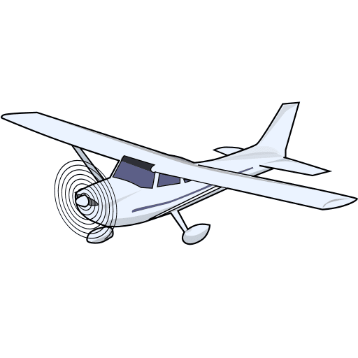
Light aircraft cockpit during instrument flight, showing a partial instrument panel with unavailable flight instruments.
Pre-Flight Lesson Instrument Flying

What happens when a flight instrument fails while you are flying without outside visual references? You may no longer have the information you normally use to maintain pitch, bank, altitude, or heading.

Partial panel flying is the technique of controlling an airplane by reference to the flight instruments that remain available and reliable. Instead of depending on a complete instrument panel, the pilot must adapt to the information still provided by the aircraft.

This skill is important in instrument flying, especially when visibility is limited. A failed instrument does not always mean that the airplane can no longer be controlled, but it can greatly reduce the pilot's available information and increase workload.

In this lesson, you will learn how to recognize instrument failure, identify the primary and supporting instruments available for aircraft control, and apply partial panel flying techniques during straight-and-level flight, climbs, descents, and timed turns.

Lesson Objective

Learn to maintain safe aircraft control when one or more flight instruments become unavailable or unreliable. Develop an effective partial panel instrument scan, interpret the remaining flight indications, and perform basic maneuvers using the instruments available in the aircraft.

01 Recognize Instrument Failure

Identify indications that may reveal an instrument malfunction and determine which flight information remains dependable.

02 Adapt Your Instrument Scan

Use the remaining primary and supporting instruments to evaluate pitch, bank, power, and aircraft performance without relying on failed indications.

03 Maintain Aircraft Control

Practice basic instrument maneuvers with a partial panel, including level flight, climbs, descents, and timed turns.

Instrument Failure Recognition

Recognizing Instrument Failure During Partial Panel Flight

A failed flight instrument does not always stop working or display an obvious warning. It may continue showing believable information even when that information is incorrect.

This is particularly important with some older gyroscopic instruments. A failing gyro may slowly drift or give an incorrect attitude indication before the pilot realizes that something is wrong. The first warning is often a disagreement between instruments.

Warning Signs You Should Not Ignore

01 Conflicting Indications

Two instruments appear to describe different flight conditions. For example, the attitude indicator suggests a turn, but the turn indicator and other reliable references do not support it.

02 Unusual Instrument Behavior

An instrument moves unexpectedly, drifts without a corresponding change in flight, or stops responding to normal aircraft movement. A frozen reading can be just as misleading as an incorrect one.

03 Failure Flags and System Warnings

A warning flag, low-vacuum indication, electrical warning, or electronic display alert may identify a problem. However, an instrument can also fail without showing an obvious warning.

Which Aircraft Systems Can Be Affected?

The instruments affected by a malfunction depend on how the airplane is equipped. A single instrument may fail, or several instruments may be affected by the loss of a shared system.

Traditional Aircraft Vacuum System or Gyro Failure

In many older airplanes, the attitude indicator and heading indicator are powered by the vacuum system. A vacuum failure can affect both instruments.

Warning clues: Low suction, a slowly drifting attitude indication, or heading indications that no longer agree with other references.

The turn coordinator may use an independent electrical power source, depending on the installation.

Aircraft Electrical System Electrical Power Failure

An alternator, generator, or electrical distribution problem may affect electrically powered flight instruments, avionics, and other equipment.

Warning clues: Low-voltage alerts, abnormal electrical indications, instrument warning flags, or displays losing power.

Which instruments remain available depends on their power sources and any installed backup systems.

Pressure Instruments Pitot-Static System Failure

A blocked pitot tube can produce unreliable airspeed indications. A static system failure can affect the airspeed indicator, altimeter, and vertical speed indicator.

Warning clues: An ASI that behaves abnormally, an altimeter that stops responding to altitude changes, or a VSI that remains near zero despite a changing flight path.

These indications depend on the type and location of the blockage.

Glass Cockpit Electronic Instrument Failure

Aircraft equipped with electronic displays may experience a display failure or a failure of an attitude and heading reference system (AHRS) or air data computer (ADC).

Warning clues: Red X symbols, invalid-data indications, display alerts, or disagreement between available displays.

A display failure does not necessarily mean that its sensors have failed. Some installations provide standby instruments or a reversionary display mode.

Example: A Slowly Failing Attitude Indicator

Imagine you are maintaining a steady heading. The attitude indicator gradually shows an increasing left bank, but the turn coordinator indicates no turn and the magnetic compass remains steady.

If the turn coordinator and compass are operating correctly, these indications suggest that the attitude indicator may be malfunctioning. The correct response is not to follow the suspicious indication blindly. Check for additional evidence before deciding which instrument has failed.

Confirming an Instrument Failure

When an instrument becomes suspicious, maintaining aircraft control takes priority over troubleshooting the failure. Use the following checks to identify the problem.

01
Compare Independent Indications

Determine which readings agree and which do not. Do not assume that the first instrument to appear unusual is the one that failed. Consider whether several instruments share the same source.

02
Check System Warnings and Power Sources

Look for relevant vacuum, electrical, or electronic failure indications. These clues can help identify whether the problem affects one instrument or an entire system.

03
Remove Unreliable Indications from the Scan

Once a failed indication has been identified, stop using it for aircraft control. Cover the failed instrument if appropriate and practical. Use a functioning standby instrument or backup display when available.

Important: Follow the Aircraft's Approved Procedures

Never assume that a particular instrument remains operational simply because it normally uses a different power source. Confirm the equipment installed in your airplane and follow its AFM/POH and applicable avionics operating procedures.

If flight information needed for safe aircraft control is lost, treat the situation as an abnormal or emergency condition as appropriate. Maintaining control always comes first.

Instrument Control and Performance

Primary and Supporting Instruments for Partial Panel Flying

In instrument flying, the pilot uses two types of information: aircraft attitude and aircraft performance. These are related, but they are not the same.

The attitude indicator (AI) directly shows pitch and bank attitude. Other instruments show the results of that attitude, such as altitude, airspeed, vertical speed, and heading changes.

In partial panel flying, the correct instrument scan depends on which instruments remain reliable. Losing the heading indicator is not the same as losing the attitude indicator.

The Difference Between the Attitude Indicator and Heading Indicator

AI Attitude Indicator

The AI provides a direct visual reference for pitch and bank. It shows the airplane's attitude relative to an artificial horizon.

When reliable, the AI is used to establish and maintain the desired flight attitude, even when another instrument is considered primary for a specific performance objective.

If the AI fails, pitch and bank must be controlled indirectly using the remaining reliable flight instruments.

HI Heading Indicator

The HI indicates the airplane's heading. In straight flight, a steady indication helps confirm that the heading is maintained.

During a turn, the movement of the heading indication provides indirect information about turning, but it does not directly display the bank angle.

If the HI fails while the AI remains reliable, the pilot still has a direct pitch and bank reference on the AI.

Full Panel vs. Partial Panel: Which Instruments Remain?

Partial panel does not always mean losing both gyroscopic instruments. The following examples show how the available control information changes.

Four Instrument Configurations

These examples assume a conventional light airplane with otherwise functioning flight and engine instruments.

1. Full Panel — Normal Instruments
AI Available HI Available

Pitch and bank: AI provides the direct attitude reference.

Heading: HI provides the main heading reference.

Supporting indications: ALT, ASI, VSI, turn coordinator (TC), and engine instruments.

2. Partial Panel — HI Failed
AI Available HI Failed

Pitch and bank: Continue using the reliable AI as the direct attitude reference.

Heading: Use the magnetic compass when its indication is appropriate and reliable.

Turning information: The TC provides turn-rate information and helps detect unintended turns.

3. Partial Panel — AI Failed
AI Failed HI Available

Pitch: Use ALT, ASI, and VSI as indirect performance references.

Bank and turning: Use the TC and the remaining reliable indications.

Heading: The HI remains a useful heading reference, provided its operation is reliable.

4. Partial Panel — AI and HI Failed
AI Failed HI Failed

Pitch: Use ALT, ASI, and VSI to evaluate pitch-related performance.

Bank and turning: Use the reliable TC to monitor turning and rolling motion.

Heading: Use the magnetic compass with an understanding of its limitations.

A standby attitude indicator or an approved backup display may provide additional information in an equipped aircraft. The instruments available depend on the actual failure and the airplane's installation. A turn coordinator does not provide an exact bank angle.

Primary and Supporting Instruments by Maneuver

The primary and supporting instruments method assigns greater attention to the instrument that best shows whether a particular flight objective is being maintained.

For example, during straight-and-level flight, altitude is the main pitch-performance reference. During a constant-airspeed climb, the airspeed indicator becomes the primary pitch-performance instrument.

When the AI is available, continue using it for direct pitch and bank control. When it is unavailable, rely on the appropriate performance indications shown below.

Basic Instrument Maneuvers — Primary References
Flight Condition Primary Pitch Performance Heading / Turn References Power-Related References
Flight Condition Straight-and-Level Flight

Maintain altitude, heading, and airspeed.

Primary Pitch Altimeter (ALT) Supporting: VSI and AI, if available. Bank / Turn HI, if available Otherwise: TC for no-turn indication; magnetic compass for heading confirmation. AI for direct bank if available. Power References ASI Primary airspeed performance indication. Check RPM or manifold pressure for engine setting.
Flight Condition Constant-Airspeed Climb or Descent

Maintain a selected airspeed while changing altitude.

Primary Pitch ASI Supporting: ALT, VSI, and AI if available. Bank / Turn HI, if available Otherwise: TC to monitor turning; compass to verify heading when suitable. AI for direct bank if available. Power References RPM / Manifold Pressure Primary reference for maintaining the intended engine power setting.
Flight Condition Constant-Rate Climb or Descent

Maintain a selected vertical speed.

Primary Pitch VSI After stabilization. Supporting: ALT, ASI, and AI if available. Bank / Turn HI, if available Otherwise: TC and magnetic compass. AI for direct bank if available. Power References ASI Primary airspeed performance indication. RPM or manifold pressure establishes engine output.
Flight Condition Standard-Rate Level Turn

Maintain altitude and a selected rate of turn.

Primary Pitch Altimeter (ALT) Supporting: VSI and AI, if available. Bank / Turn Turn Coordinator (TC) Primary turn-rate indication. AI shows bank directly if available. HI or compass provides heading information. Power References ASI Primary airspeed performance indication. RPM or manifold pressure supports power control.

These primary references describe stabilized flight conditions. During maneuver entries, level-offs, or power changes, the instrument requiring the most attention may change. The detailed cross-check and control techniques are covered in the following chapters.

Direct Attitude Control vs. Performance Indications

When the AI Is Working

Use the attitude indicator to establish and monitor pitch and bank directly. Then verify the result using the appropriate primary performance instrument. For example, the AI shows the pitch attitude, while the altimeter confirms whether level flight is maintained.

When the AI Is Unavailable

Pitch changes must be evaluated through the airspeed, altitude, and vertical speed indications. The TC provides information about turning and rolling. These instruments do not reproduce the AI's direct presentation of pitch and bank.

Airspeed Is Not an Engine Power Gauge

The airspeed indicator is described as primary for power in some instrument-flying reference charts because it shows the performance being maintained at a given altitude.

However, the ASI does not measure engine power directly. The tachometer and manifold pressure gauge, when installed, indicate engine operating conditions. A correct instrument scan uses both the selected power setting and the resulting aircraft performance.

Practical Flight Technique

Straight-and-Level Flight with Partial Panel — Step by Step

In straight-and-level flight, the pilot must keep the airplane at a selected altitude and heading while maintaining a safe, appropriate airspeed. With partial panel, this requires a disciplined instrument cross-check and small, smooth control corrections.

The instrument scan changes according to the failure. Use the sequence that matches the instruments still available in your airplane.

Instrument Scan: Which Instrument Comes Next?

Follow the order shown below as a practice pattern. Move continuously between instruments rather than staring at one indication. Return to the first instrument and repeat. Give extra attention to an indication that begins to change, without neglecting the others.

Sequence A — Heading Indicator Failed, Attitude Indicator Working
AI Available HI Failed
  1. AI Check pitch attitude and bank directly.
  2. ALT Confirm that the selected altitude is maintained.
  3. TC Check for an unintended turn.
  4. ASI Check the selected airspeed.
  5. VSI Check for a developing climb or descent.
  6. Compass Confirm heading when the airplane is steady.
Return to AI → ALT → TC → ASI → VSI. Check the compass periodically during stable, unaccelerated flight.

Key point: The reliable AI remains your direct attitude reference. Do not abandon it simply because the HI has failed.

Sequence B — Attitude Indicator Failed, Heading Indicator Working
AI Failed HI Available
  1. TC Check for turning or rolling movement.
  2. ALT Check altitude and its direction of change.
  3. HI Check that the selected heading remains steady.
  4. ASI Check airspeed and its trend.
  5. VSI Confirm the vertical-speed trend.
  6. TC Return immediately to the turn reference.
Repeat continuously: TC → ALT → HI → ASI → VSI → TC.

Key point: Without an AI, the TC and HI help monitor turning, while the ALT, ASI, and VSI provide indirect pitch-performance information. Use the HI only if it has been confirmed reliable.

Sequence C — Attitude Indicator and Heading Indicator Failed
AI Failed HI Failed
  1. TC Detect unintended turning motion.
  2. ALT Monitor the selected altitude.
  3. ASI Check airspeed and possible pitch-related changes.
  4. VSI Confirm whether altitude is increasing or decreasing.
  5. Compass Verify heading when flight is stable.
  6. TC Return to the turn reference.
Repeat: TC → ALT → ASI → VSI → TC. Include the compass when its reading is suitable.

Key point: The TC shows turning information, not the airplane's exact bank angle. The magnetic compass provides heading information but has limitations during turns and acceleration.

In all three sequences, include a brief check of the tachometer or manifold pressure gauge when evaluating airspeed or changing power. These are flexible scanning patterns, not fixed intervals between instruments.

Straight-and-Level Flight: Control Procedure

1 Maintain Straight Flight

First, prevent an unintended turn. Which instrument you look at first depends on whether the AI is available.

Look First

AI available: Check the bank indication on the attitude indicator.

AI unavailable: Check the turn coordinator. The goal is to stop unintended turning motion.

Cross-Check

Check the reliable HI for heading movement, if available. Otherwise, use the magnetic compass to confirm heading when the airplane is stable.

Use the TC to check turning information and coordination.

Control Action and Expected Indication

If the airplane begins an unintended turn, use small, coordinated aileron and rudder inputs to stop it. With a reliable AI, restore the appropriate bank attitude. Without an AI, use the TC to arrest the turn.

Expected result: The TC returns toward its no-turn indication, and the reliable heading reference becomes steady. If the airplane is not on the desired heading, a separate controlled correction may be required.

2 Maintain the Selected Altitude

Once turning motion is controlled, check whether the airplane is maintaining altitude.

Look First

ALT: Compare the indicated altitude with the selected altitude. Watch whether the indication is remaining steady, increasing, or decreasing.

Cross-Check

AI available: Check the pitch attitude directly.

AI unavailable: Check the VSI for the vertical-speed trend and the ASI for airspeed changes. Keep returning to the TC or reliable heading reference.

Control Action and Expected Indication

If altitude is slowly decreasing and airspeed remains safely within the appropriate range, make a small, smooth aft-elevator correction to arrest the descent. If altitude is increasing, use a small forward-elevator correction.

Expected result: The VSI trends toward zero, and the altimeter's movement slows. Adjust as needed to return to the selected altitude, then remove the extra control pressure as level flight is restored.

3 Maintain the Desired Airspeed

When altitude and heading are under control, confirm that the airplane is maintaining the desired airspeed.

Look First

ASI: Compare the indicated airspeed with the desired speed. Determine whether airspeed is steady, increasing, or decreasing.

Cross-Check

ALT and VSI: Check whether the airplane is also climbing or descending.

RPM or manifold pressure: Verify the engine power setting. If the AI works, also check pitch and bank.

Control Action and Expected Indication

If altitude is steady but airspeed is below the selected value, an appropriate increase in power may be needed. If airspeed is above the desired value, a power reduction may be appropriate.

Expected result: The engine instruments show the new power setting, and airspeed trends toward the selected value. Monitor ALT and the available bank or turn indications while the airplane responds.

4 Recheck, Stabilize, and Trim

After any control or power adjustment, return to the appropriate instrument scan. Do not keep making corrections before the airplane has had time to respond.

Look First

Return to the AI if it is available. Otherwise, return to the TC and ALT.

Cross-Check

Confirm stable altitude, safe and appropriate airspeed, and the desired heading using the remaining reliable instruments.

Control Action and Expected Indication

When the flight condition is stable, use trim to reduce sustained control pressure. Continue scanning while trimming because the airplane may respond to a small adjustment.

Expected result: Altitude, heading, and airspeed remain stable with less control pressure. The scan continues throughout the flight.

Applying the Scan: Two Practical Examples

Example 1 — AI Failed, Altitude Decreasing

The AI is unavailable. The TC indicates no turn, but the altimeter shows a gradual altitude loss. The VSI indicates a descent, and airspeed is increasing.

Scan: TC → ALT → ASI → VSI → HI, if reliable → TC.

Interpret: The airplane is descending and accelerating. The readings are consistent with an excessive nose-low flight condition, but the pilot must also consider the power setting.

Correct: Make a smooth pitch correction to arrest the descent while continuing to monitor airspeed and turning. Verify that altitude begins to stabilize without creating a large opposite deviation.

Example 2 — HI Failed, Unintended Turn

The AI is working, but the HI is unavailable. The AI shows a slight right bank, and the TC confirms a right turn. The altimeter remains approximately steady.

Scan: AI → TC → ALT → ASI → VSI → AI. Check the compass once flight is stable.

Interpret: The airplane is turning even though altitude is being maintained.

Correct: Use a small, coordinated bank correction to stop the turn. Confirm the AI shows the appropriate attitude and the TC returns toward no turn. Then verify heading with the magnetic compass.

Important: Do Not Chase Individual Instruments

Partial panel flying requires continuous cross-checking. The altimeter shows altitude, but it does not directly show pitch attitude. The VSI may lag behind the airplane's actual movement. The TC indicates turning and rolling information, but not exact bank angle.

Use small, smooth corrections and verify their effect before making further adjustments. Avoid aggressive pitch changes simply to regain a small altitude deviation. If the airplane is approaching an unsafe airspeed or an unusual attitude, aircraft control and the appropriate recovery procedure take priority over maintaining an exact altitude.

These are training examples, not aircraft-specific emergency procedures. Practice partial panel flying with a qualified instructor and follow the aircraft's approved procedures and limitations.

Pilot Resources

Pilot Supplies & Training Essentials

Explore Pilot Mall →
Partial Panel Flight Technique

Partial Panel Climbs, Descents, and Level-Offs

Without a working attitude indicator (AI), you cannot see pitch attitude directly. Without a working heading indicator (HI), you also lose your normal heading reference. This makes changing altitude more demanding than in full-panel instrument flying.

The main challenge is the transition. When you change pitch or power, the airspeed indicator (ASI), vertical speed indicator (VSI), and altimeter (ALT) respond at different rates. Meanwhile, the turn coordinator (TC) must remain part of your scan so that an unnoticed turn does not develop.

Training configuration: The procedures below assume the AI and HI are unavailable, while the TC, ASI, ALT, VSI, magnetic compass, and engine instruments are reliable.

If your AI remains functional, continue using it for direct pitch and bank control. These examples focus on flying without that direct attitude reference.

Constant-Airspeed Climbs and Descents — Partial Panel

Without the AI, you cannot select a precise nose-up or nose-down attitude by looking at an artificial horizon. Instead, establish the maneuver smoothly, then use airspeed as your main pitch-performance reference. The TC must be checked repeatedly to prevent unintended turning.

Partial Panel Scan — Constant Airspeed Repeat this instrument sequence:
TC → ASI → RPM / MP → TC → VSI → ALT → Repeat

TC: Detect unintended turning. ASI: Evaluate pitch-related performance. RPM / MP: Confirm power. VSI and ALT: Confirm the vertical flight path. Briefly check the magnetic compass when its indication is suitable.

1
Establish the Maneuver Without an AI

Check the TC for unintended turning. Establish the appropriate climb or descent with a small, smooth pitch change and the intended power setting. Since there is no AI, avoid trying to estimate an exact pitch angle. Observe the ASI as the airplane responds.

2
Let the ASI Guide Pitch Corrections

Once power is established, an airspeed below the selected value generally calls for a small reduction in nose-up pitch, or a slightly more nose-down attitude. Airspeed above the selected value generally calls for the opposite correction. Check power before interpreting every airspeed change as a pitch error.

3
Confirm the Vertical Flight Path

Check that the VSI shows the intended climb or descent trend and that the ALT changes in the same direction. Return to the TC frequently. If the ASI approaches the selected speed, avoid making further pitch changes before the aircraft response stabilizes.

Expected indications: ASI stabilizes near the selected airspeed; VSI and ALT confirm a climb or descent; TC shows no unintended turning.

Constant-Rate Climbs and Descents — Partial Panel

The main difficulty here is that the VSI does not provide an immediate, direct pitch indication. During the entry, monitor airspeed closely while the vertical-speed indication develops. After the VSI stabilizes, use it as the primary pitch-performance reference.

Partial Panel Scan — Constant Vertical Rate During the entry:
TC → ASI → VSI → RPM / MP → TC
After the vertical rate stabilizes:
TC → VSI → ASI → TC → ALT → RPM / MP
1
Establish the Desired Rate

Use a small pitch change and an appropriate power setting while checking the TC. Watch the VSI develop toward the desired rate, but do not chase its initial movement. Monitor the ASI throughout the transition.

2
Control the Rate Without an Attitude Indicator

When the VSI has stabilized, make small pitch corrections to hold the selected vertical rate. Allow time for the VSI to respond. Confirm the direction of altitude change on the ALT rather than relying on the VSI alone.

3
Protect Airspeed and Heading

If vertical speed is correct but airspeed is decreasing, check whether additional power is needed. Coordinate any power change with the pitch correction required to maintain the selected vertical rate. Keep returning to the TC so that heading control is not neglected.

Expected indications: VSI remains near the selected rate; ASI remains in the intended safe range; ALT changes steadily; TC confirms that no unwanted turn is developing.

Partial Panel Level-Off — Capturing Altitude Without an AI

During a partial panel level-off, the pilot cannot use the artificial horizon to identify the level-flight attitude. Instead, the transition is judged by how the ALT and VSI respond, while the ASI and engine instruments confirm that the airplane is stabilizing at the intended speed.

Partial Panel Scan — Level-Off Approaching the selected altitude:
ALT → TC → VSI → ASI → RPM / MP → ALT
1
Anticipate the Altitude Capture

Use the ALT to judge the remaining altitude and the VSI to judge how quickly the airplane is approaching it. Begin the level-off early enough to allow the vertical rate to decrease before the selected altitude is reached. Check the TC during the transition.

2
Reduce the Vertical Rate Smoothly

Apply a small elevator correction toward the level-flight attitude. Watch the ALT movement slow and the VSI trend toward zero. Because the VSI may lag, do not wait for an exact zero indication before evaluating the response.

3
Confirm the New Flight Condition

Coordinate power with the intended level-flight airspeed. Check that the ALT stops moving at the selected altitude, the VSI approaches zero, and the ASI remains appropriate. Return to the TC and verify heading with the compass once flight is stable.

Expected indications: ALT stabilizes at the selected altitude; VSI approaches zero; ASI reaches the intended level-flight speed; TC indicates no unintended turn.

What Makes Partial Panel Transitions Difficult?

VSI Lag Can Encourage Overcontrol

After changing pitch, the airplane may already be responding while the VSI is still catching up. Repeated corrections based only on the VSI can create unwanted pitch oscillations. Always compare it with the ALT and the ASI.

Pitch Changes Can Hide an Unwanted Turn

Without the AI, attention may shift toward airspeed and vertical speed. An unintended bank or turn can develop while the pilot concentrates on altitude. Keep the TC in every active scan and use the compass when appropriate.

Partial Panel Control: One Correction, Then Cross-Check

The goal is not to reproduce the missing attitude indicator by guessing pitch or bank angles. Use the available instruments to establish a stable flight path, make small corrections, and confirm the actual result.

These scan sequences are training patterns, not mandatory fixed orders. Adjust the scan to the aircraft, the available instruments, and the most urgent deviation. If an instrument becomes unreliable, it must not continue to serve as a flight-control reference.

Partial Panel Heading Control

Timed Turns and Magnetic Compass Turns — Step by Step

In this partial panel exercise, both the Attitude Indicator (AI) and the Heading Indicator (HI) are unavailable. The pilot has no direct artificial-horizon reference for pitch and bank, and no gyroscopic heading indication.

To change heading, the pilot must use the remaining reliable instruments. The Turn Coordinator (TC) provides turning information, the clock measures the duration of the turn, and the magnetic compass provides a heading reference.

The challenge is to maintain a controlled turn rate without losing altitude or allowing airspeed to change excessively. The TC must therefore be checked repeatedly against the altimeter (ALT), airspeed indicator (ASI), and other available performance instruments.

Partial Panel Configuration Used in This Exercise
AI — Unavailable HI — Unavailable TC — Available ALT / ASI / VSI — Available

The magnetic compass, clock, and engine instruments are also assumed reliable. Both the AI and HI remain unavailable throughout the following procedures. The TC provides rate-of-turn information, but it does not show the airplane's exact bank angle.

Timed Turns Using the Turn Coordinator

A timed turn uses a known rate of turn and a measured period of time to produce an approximate heading change. This technique is useful when the magnetic compass cannot be followed precisely during the turn.

At a standard rate, the airplane turns approximately 3° per second. At a half-standard rate, it turns 1.5° per second. The TC must provide a reliable and appropriately calibrated turn-rate indication.

Calculate the Time Required
Heading Change ÷ Turn Rate = Time
Heading Change Standard Rate (3°/s) Half-Standard Rate (1.5°/s)
30° 10 seconds 20 seconds
45° 15 seconds 30 seconds
90° 30 seconds 60 seconds
180° 60 seconds 120 seconds

These calculations assume the selected rate is maintained. For best accuracy, turn entry and recovery should be performed at similar roll rates. The TC should be calibrated during normal instrument training, before relying on it for a timed turn after a failure.

Instrument Scan — Timed Turn Repeat during the turn:
TC → Clock → ALT → ASI → TC

TC: Maintain the selected rate of turn. Clock: Track elapsed time. ALT: Maintain altitude without a direct pitch reference. ASI: Monitor airspeed. Include the VSI and engine instruments when needed.

The magnetic compass is used to establish the starting heading and verify the final heading, once the airplane is stable.

1 Determine the Turn and Calculate the Time
Look First

Magnetic compass: Read the present heading while maintaining stable, unaccelerated flight.

Cross-Check

TC: Confirm no unintended turn. ALT and ASI: Check stable altitude and appropriate airspeed.

Preparation

Determine the required heading change and direction. Divide the number of degrees by 3 for a standard-rate turn, or by 1.5 for a half-standard-rate turn. Prepare to start timing as the roll-in begins.

2 Enter the Turn Using the TC
Look First

TC: Watch the turn-rate indication develop toward the calibrated standard or half-standard rate.

Clock: Begin timing as the roll-in starts.

Cross-Check

ALT: Monitor altitude as the turn begins. ASI: Confirm appropriate airspeed.

Control Action and Expected Indications

Apply smooth, coordinated aileron and rudder inputs. Establish the selected rate using the TC, without trying to estimate a bank angle from the miniature aircraft symbol.

Expected: The TC approaches the selected rate indication. The ALT remains approximately steady, and the ASI remains in the intended range.

3 Hold the Rate Without Losing Altitude
Look First

TC: Maintain the selected turn rate. Clock: Monitor elapsed time.

Cross-Check

ALT: Detect an altitude deviation. ASI: Check for an airspeed change. VSI: Confirm the vertical trend.

Control Action and Expected Indications

Use small elevator corrections when the reliable altitude and vertical-speed indications show that a correction is needed. Avoid overcorrecting in response to VSI lag.

Continue checking the TC because a pitch correction must not distract you from maintaining the selected turn rate.

Expected: The TC holds the desired rate, the clock advances toward the calculated time, and altitude and airspeed remain controlled.

4 Roll Out at the Calculated Time
Look First

Clock: Identify when the calculated turn time has elapsed.

TC: Monitor the decreasing rate of turn during roll-out.

Cross-Check

ALT and ASI: Confirm the airplane remains controlled during the transition back to straight flight.

Control Action and Expected Indications

Begin the roll-out when the computed time expires. Use a smooth roll-out comparable to the roll-in. This helps balance the additional heading changes during the two transitions.

Expected: The TC returns toward its no-turn indication. The altimeter remains stable and no opposite turn develops.

5 Confirm the Final Heading
Look First

TC: Confirm no turning motion.

Magnetic compass: Allow the indication to settle before reading the new heading.

Cross-Check

ALT and ASI: Confirm stabilized flight. Apply any known compass deviation correction when appropriate.

Control Action and Expected Indications

Compare the settled compass indication with the desired heading. If necessary, calculate a small additional timed correction and verify the result.

Example: A 90° Timed Turn

The airplane is established in level flight on heading 090°. The pilot wants to turn right to heading 180°.

Calculation: 90° ÷ 3° per second = 30 seconds.

During the turn: TC → Clock → ALT → ASI → TC. Maintain the calibrated standard-rate indication and monitor altitude throughout the turn.

After 30 seconds: Begin the roll-out. Confirm no turn on the TC, allow the magnetic compass to stabilize, and compare its reading with the target heading of 180°.

Compass rose showing standard-rate timed turns with both the attitude indicator and heading indicator unavailable: 45 degrees in 15 seconds, 90 degrees in 30 seconds, 135 degrees in 45 seconds, and 180 degrees in 60 seconds.
Standard-rate timed turns at 3° per second: 15 seconds = 45°, 30 seconds = 90°, 45 seconds = 135°, 60 seconds = 180°.

Magnetic Compass Turns

A magnetic compass turn uses the compass as the heading reference, but the compass must not be treated like a functioning HI. Its indications can lead or lag the airplane's actual heading during a turn.

In the Northern Hemisphere, the important rule is undershoot north, overshoot south. The amount of correction depends on latitude, the target heading, and the airplane's turning characteristics.

Turning Toward North

The magnetic compass tends to lag the actual turn. Begin the roll-out before the compass reaches the desired northerly indication.

The required lead generally increases with latitude. Allow for normal roll-out characteristics as well.

Turning Toward South

The magnetic compass tends to lead the actual turn. The compass may display the desired southerly heading before the airplane has reached it.

Continue beyond the target compass indication by an appropriate amount, allowing for the roll-out, then verify the final heading.

Instrument Scan — Compass Turn Repeat during the turn:
TC → Compass → ALT → ASI → TC

The TC controls the rate of turn. The compass indicates the approximate heading progression, subject to turning errors. The ALT and ASI remain essential for monitoring aircraft performance.

1 Determine the Compass Correction

From the stabilized starting heading, identify the desired heading and estimate the appropriate compass-turning correction. Consider magnetic dip, latitude, target heading, and the expected roll-out.

2 Establish the Turn with the TC
Look First

TC: Establish and maintain a controlled rate of turn.

Cross-Check

Compass: Monitor heading progression. ALT and ASI: Monitor aircraft performance throughout the turn.

Control Action and Expected Indications

Use small coordinated control inputs to maintain the selected rate. Do not chase every movement of the compass card. Continue the TC → Compass → ALT → ASI cross-check.

3 Anticipate the Roll-Out

Begin reducing the turn at the anticipated compass indication. Apply the appropriate north or south correction and account for roll-out.

Expected Indications

The TC returns toward its no-turn indication. The ALT and ASI remain controlled. The compass indication may continue settling after the turn stops.

4 Verify and Correct the Heading
Look First

TC: Confirm that the turn has stopped.

Compass: Read the stabilized heading.

Cross-Check

ALT, ASI, and VSI: Confirm a stable flight path. Check engine instruments if the airspeed is not as expected.

Control Action and Expected Indications

If the compass indicates a remaining heading error, make a small controlled correction using the reliable TC and verify the heading again after the airplane stabilizes.

Important: Use Only Reliable Instruments

Use only the remaining reliable instruments to control the airplane and verify the results of each turn. Never return to an indication already identified as unreliable.

The TC does not display the exact bank angle. The magnetic compass is affected by turning and acceleration errors. The VSI may lag. A correct partial panel scan must account for all three limitations.

If the TC becomes unreliable, the timed-turn procedure described here is no longer suitable. Use any reliable independent backup instruments and follow the aircraft's approved abnormal or emergency procedures.

These procedures are training examples for appropriately equipped aircraft. Practice them with a qualified instrument instructor.

IFR Decision-Making

Partial Panel Approaches and ATC Assistance

With both the Attitude Indicator (AI) and Heading Indicator (HI) unavailable, maintaining aircraft control requires greater attention and leaves less time for navigation and approach preparation.

If this happens in instrument meteorological conditions (IMC), the immediate objective is not to continue the flight plan as originally intended. It is to identify a safe way to reach visual conditions or an appropriate landing airport.

Priority: Aircraft Control Before Approach Planning

Maintain aircraft control using the remaining reliable instruments. Avoid unnecessary maneuvering and high-workload procedures. Once the airplane is stable, contact Air Traffic Control (ATC) and request the assistance needed for the situation.

Before Attempting a Partial Panel Approach

Losing both gyroscopic references does not necessarily mean that the navigation equipment has also failed. However, working navigation instruments do not guarantee that the pilot can safely fly an instrument approach.

01 Consider the Weather

Determine whether nearby visual meteorological conditions (VMC) offer a safer option. A route toward better weather or a suitable alternate airport may reduce the difficulty of the situation.

02 Check Remaining Navigation Equipment

Identify whether an independent localizer, glideslope, VOR, or approved GPS installation is still operating reliably. Do not assume that a navigation display remains usable after a related system failure.

03 Reduce the Workload

Ask ATC for assistance before becoming overloaded. Requesting a suitable route, additional time, radar vectors, or a different destination may simplify the flight.

04 Evaluate the Entire Approach

Consider weather, available guidance, terrain clearance, approach minima, and the missed approach. A procedure is not a safe choice simply because its navigation receiver still works.

Reporting the Failure and Requesting ATC Assistance

Tell ATC which instruments are unavailable and what assistance you need. A simple equipment report is more useful than only saying that you are flying partial panel.

Example Radio Call
"Approach, N123AB. We have lost both our attitude indicator and heading indicator. We are maintaining control using partial panel. Request no-gyro vectors toward a suitable airport."

Adjust the call to describe the actual aircraft condition. If safe control is seriously threatened, declare an emergency and request priority assistance. Report the nature of any additional equipment limitations.

No-Gyro Vectors: How ATC Can Help

With the HI unavailable, ordinary radar instructions that require flying a specified magnetic heading may be difficult to follow accurately.

During no-gyro vectoring, ATC can use radar to determine when the airplane should begin and stop turning. The pilot does not need to calculate the heading change from a functioning HI.

No-Gyro Radar Vector ATC: "TURN RIGHT."

Begin a standard-rate right turn using the reliable Turn Coordinator (TC). Continue monitoring altitude and airspeed.

ATC: "STOP TURN."

Stop the turn promptly. Use the TC to confirm that turning motion has ended. Maintain the resulting flight path until further instructions.

No-Gyro Radar Approach ATC: "MAKE HALF-STANDARD RATE TURNS."

During a no-gyro surveillance or precision radar approach, ATC may instruct the pilot to use half-standard-rate turns after alignment with the final approach course.

Use the appropriate TC rate indication and continue following the controller's turn and stop-turn instructions.

No-Gyro Vectors Are Not the Same as a No-Gyro Radar Approach

No-gyro vectors provide radar assistance with changes of direction. They may help position an airplane for another type of approach.

A no-gyro radar approach is a specific radar approach service. Depending on the type offered, ATC may provide lateral guidance and, for a precision radar approach, vertical guidance as well. These services are not available at every airport.

Neither service restores the failed attitude indicator. The pilot must still control the airplane using the reliable remaining instruments.

Flying an Instrument Approach with Partial Panel

If weather conditions, available equipment, and aircraft controllability permit an instrument approach, the pilot must distinguish navigation guidance from aircraft control.

1
Confirm the Approach Guidance Is Reliable

A functioning localizer or GPS course indication can provide lateral navigation information. It does not show the airplane's bank angle. A glideslope indication provides vertical guidance, not pitch attitude.

2
Maintain an Independent Control Cross-Check

Continue using the reliable TC to monitor turning, the ASI to monitor airspeed, and the ALT and VSI to monitor vertical performance. Do not abandon aircraft control to concentrate exclusively on the navigation needle.

3
Respect Altitudes and Approach Minima

Follow the applicable altitude restrictions and published procedure requirements. Do not descend below the authorized approach minimum unless the requirements for continuing to land are met. Prepare for the possibility of a missed approach.

4
Be Prepared to Discontinue the Approach

If aircraft control, navigation information, or the ability to complete the approach becomes uncertain, do not force the airplane toward the runway. Advise ATC immediately and follow the appropriate missed approach or emergency plan.

Practical Scenario: Both AI and HI Fail in IMC

Choosing the Safest Way to Land

You are flying IFR in cloud. Both the AI and HI have failed, but the TC, ALT, ASI, and VSI remain reliable. ATC has radar contact. You are approaching your destination airport, where the reported weather is near the published approach minima.

First Decision

Do not assume that continuing to the original destination is the safest option. Tell ATC about both failures and request available assistance. Consider an airport with better weather or easier approach conditions.

Second Decision

If an instrument approach is still necessary, determine whether the available aircraft instruments, navigation guidance, ATC assistance, and missed approach options make it feasible. If not, communicate that limitation to ATC.

Final Priority: A Safe Landing, Not Completion of the Original Plan

A partial panel approach with both the AI and HI unavailable is a high-workload operation, particularly in IMC. No-gyro vectors may reduce navigation workload, but they cannot replace a reliable attitude reference.

Use available backup equipment, obtain ATC assistance early, and choose the least demanding safe option available. If you cannot confidently maintain aircraft control or safely execute the approach, communicate the problem and seek emergency assistance.

Knowledge Check

Partial Panel Practice and Review Questions

Use the following situations to test your understanding of partial panel instrument flying. Before opening each answer, identify the instruments you would use, the action you would take, and the indications that would confirm the result.

Exercise Configuration
AI — Unavailable HI — Unavailable TC — Available ALT / ASI / VSI — Available

Both the Attitude Indicator (AI) and Heading Indicator (HI) are unavailable in every exercise. The Turn Coordinator (TC), Altimeter (ALT), Airspeed Indicator (ASI), Vertical Speed Indicator (VSI), magnetic compass, and engine instruments are assumed reliable.

Practice Scenarios

01 An Unintended Turn in Level Flight

You are flying in IMC at a selected altitude of 4,500 feet. Both the AI and HI are unavailable. During the instrument scan, you notice the following indications.

TC Slight right turn
ALT 4,500 feet
ASI Stable
VSI Near zero

Your task: Which instrument should receive immediate attention? What correction is needed? How will you verify that straight flight has been restored?

Show the recommended action

1. Look at the TC. It indicates an unintended turn, even though altitude and airspeed remain stable.

2. Correct smoothly. Use small, coordinated aileron and rudder inputs to stop the right turn.

3. Cross-check. Confirm that the TC returns toward its no-turn indication. Continue checking ALT and ASI. Once stable, check the magnetic compass and determine whether a heading correction is required.

02 Leveling Off Without an Attitude Indicator

You are climbing toward an assigned altitude of 5,000 feet. Both the AI and HI are unavailable. The climb has been stable, but you must now capture the selected altitude.

ALT 4,940 feet
VSI +500 fpm
TC No turn
ASI Stable climb speed

Your task: Should you wait until the ALT reads 5,000 feet? Which instruments will show that the level-off is progressing correctly?

Show the recommended action

1. Anticipate the level-off. At 500 fpm, begin the transition before reaching 5,000 feet, using an appropriate lead for the airplane's response.

2. Make a smooth correction. Reduce the climb attitude gradually, without relying on the unavailable AI. Coordinate power with the intended level-flight airspeed.

3. Cross-check. ALT → VSI → TC → ASI → ALT. The VSI should trend toward zero, the altimeter should stabilize near 5,000 feet, and the TC should continue showing no unintended turn.

Do not chase the VSI if its indication lags behind the aircraft's response.

03 Both AI and HI Fail During an IFR Arrival

You are approaching your destination in IMC. Both the AI and HI are unavailable, but the TC and the other essential flight instruments remain reliable.

ATC has radar contact. Weather at your destination is near the published approach minima, while another suitable airport reports better weather.

Your task: What should you tell ATC? What assistance can you request? Should you automatically continue toward your original destination?

Show the recommended action

1. Maintain control. Use the reliable TC, ALT, ASI, and VSI to stabilize the airplane.

2. Inform ATC. Report that both the attitude indicator and heading indicator are unavailable. Request assistance, such as no-gyro vectors, and declare an emergency if the circumstances warrant it.

3. Consider the safer destination. Better weather and a less demanding approach may be preferable. Determine whether the aircraft can safely complete the required procedure.

4. Remember the limitation. ATC radar assistance can reduce navigation workload, but it cannot replace the lost attitude indication or the pilot's responsibility to control the airplane.

Review Questions

Answer each question before opening the explanation. These questions cover instrument selection, cross-check, partial panel maneuvers, timed turns, compass errors, and ATC assistance.

Question 01 What indications may reveal that an attitude indicator is unreliable?
Show answer

A drifting, frozen, or inconsistent indication may reveal a failure. Compare the AI with other independent, reliable instruments. A failure flag or system warning may also provide a clue.

Question 02 With both the AI and HI unavailable, which instruments help monitor straight-and-level flight?
Show answer

ALT is the main pitch-performance reference. TC helps detect unintended turning. ASI monitors airspeed, and VSI confirms the vertical trend. The magnetic compass provides heading information during stable flight.

Question 03 During a partial panel constant-airspeed climb, which instrument is primary for pitch performance?
Show answer

The ASI. With the climb power established, the pilot uses airspeed trends to evaluate pitch corrections. TC, ALT, and VSI provide supporting information.

Question 04 Which instrument becomes primary after a constant-rate climb or descent stabilizes?
Show answer

The VSI becomes the primary vertical-rate performance reference. The ASI must still be checked to maintain a safe airspeed, and the ALT confirms the continuing altitude change.

Question 05 Why is reacting immediately to every VSI movement particularly dangerous during partial panel flight?
Show answer

The VSI may lag behind the actual aircraft response. Repeated corrections made before the previous adjustment takes effect can cause overcontrol. Compare VSI indications with ALT and ASI trends.

Question 06 How long is a 120° heading change at a standard rate of 3° per second?
Show answer

40 seconds.

120° ÷ 3° per second = 40 seconds. Maintain the calibrated TC turn-rate indication and verify the resulting heading with the compass after the airplane stabilizes.

Question 07 In the Northern Hemisphere, what is the basic rule for compass turns toward north and south?
Show answer

Undershoot north, overshoot south.

Magnetic compass turning error depends on latitude and the heading approached. The pilot must also allow for roll-out characteristics and verify the final heading once the compass settles.

Question 08 During no-gyro vectoring, what does “STOP TURN” mean, and what must the pilot continue monitoring?
Show answer

Stop the turn promptly and use the reliable TC to confirm that turning motion has ended.

Continue monitoring altitude, airspeed, and the remaining reliable instruments. ATC provides directional assistance; the pilot remains responsible for aircraft control.

Final Training Reminder

Partial panel proficiency depends on recognizing unreliable indications, selecting the correct remaining references, and making controlled adjustments without overreacting. These skills must be developed through supervised instrument training, not only through written exercises.

Practice instrument failures with a qualified instructor and use the procedures and limitations applicable to the aircraft being flown.

error:
Study flight
Logo